IoT Based Voice Controlled Home Automation Using NodeMCU & Android.
- Get link
- X
- Other Apps
- Components Required
- Block Diagram of Voice Controlled Home Automation using ESP8266
- Circuit: Wifi & Voice Controlled Home Automation Using ESP8266
- Android App Voice Controlled Home Automation
- Creating an Android App Using MIT App Inventor:
- Home Automation App Download Link:
- Code to find NodeMCU IP Address
- Source Code/Program.

Components Required
Following are the list of the components that are required for making Voice Controlled Home Automation Project Using NodeMCU ESP8266 WiFi Module.
| S.N. | Components | Description | Quantity |
|---|---|---|---|
| 1 | NodeMCU | ESP8266-12E Board | 1 |
| 2 | Relay Module | 4-Channel 5V NPN Relay Module | 1 |
| 3 | LED | 5mm LED of Any Color | 4 |
| 4 | Resistor | 220 ohm | 4 |
| 5 | Power Supply | 5V, 1A Power Adapter | 1 |
| 6 | Connecting Wires | Jumper Wires | 10 |
| 7 | Breadboard | – | 1 |
Circuit: Wifi & Voice Controlled Home Automation Using ESP8266
Here we will use a single channel relay and 3 LEDs connected to NodeMCU GPIOs. Simulating them as home appliances. If you have 4 channel relay you can connect them as below.

| NodeMCU ESP8266 GPIOs | Relay Input Pin |
| GND | GND |
| GPIO Pin D1 | Input Pin 1 |
| GPIO Pin D2 | Input Pin 2 |
| GPIO Pin D3 | Input Pin 3 |
| GPIO Pin D4 | Input Pin 4 |
| Vin/5v | Vcc |

Connect Relay Input Pin with NodeMCU ESP8266 as follows:
Similarly, Connect the 4 output to 4 different LEDs as shown in the figure above.
Android App Voice Controlled Home Automation
The Android App will send a string that must be interpreted by the code to activate each one of the relays defined as follows:
Relay1:
Turn-On: “r1on”;
Turn-Off: “r1off”;
Relay2:
Turn-On: “r2on”;
Turn-Off: “r2off”
Relay3:
Turn-On: “r3on”;
Turn-Off: “r3off”
Relay4:
Turn-On: “r4on”;
Turn-Off: “r4off”
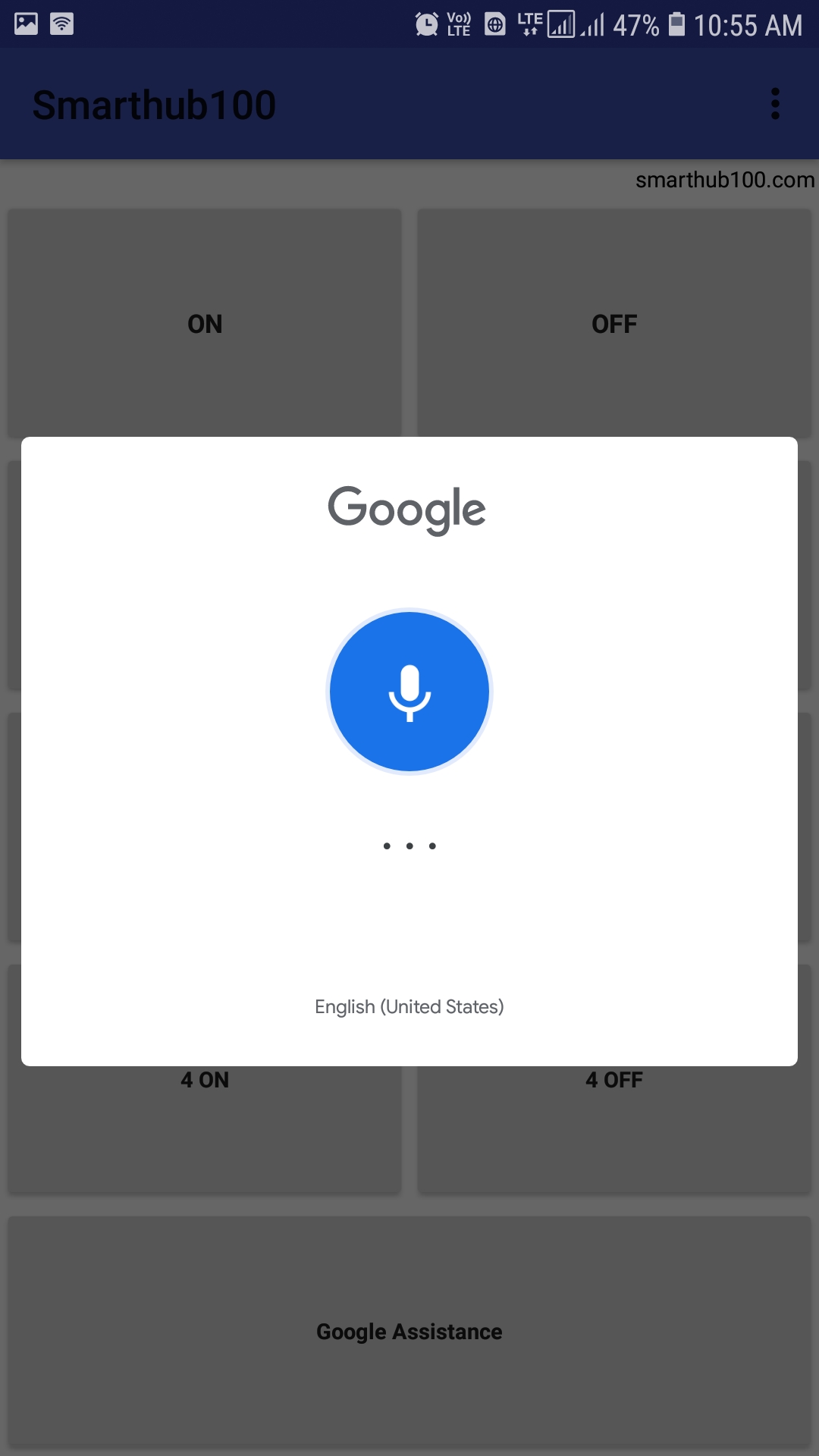
Whenever Android App sends as a command: “r1on”, Relay1 must be turn on. We have also defined “group commands” to turn-on all the relay (“All ON”) and turn-off (“All OFF”) simultaneity all devices. Similarly, the voice input option is also given which when clicked gives a pop up for Google Assistant to Accept Voice Command.
Creating an Android App Using MIT App Inventor:
You can skip this step. Because I have provided the link of the android app file that is directly downloadable. Not only that, but I have also added the link of . so that you can modify the app according to your requirements.
To create an Android App Visit MIT App Inventor website and create a new project.
The main components of this app are as shown in the screenshot below:
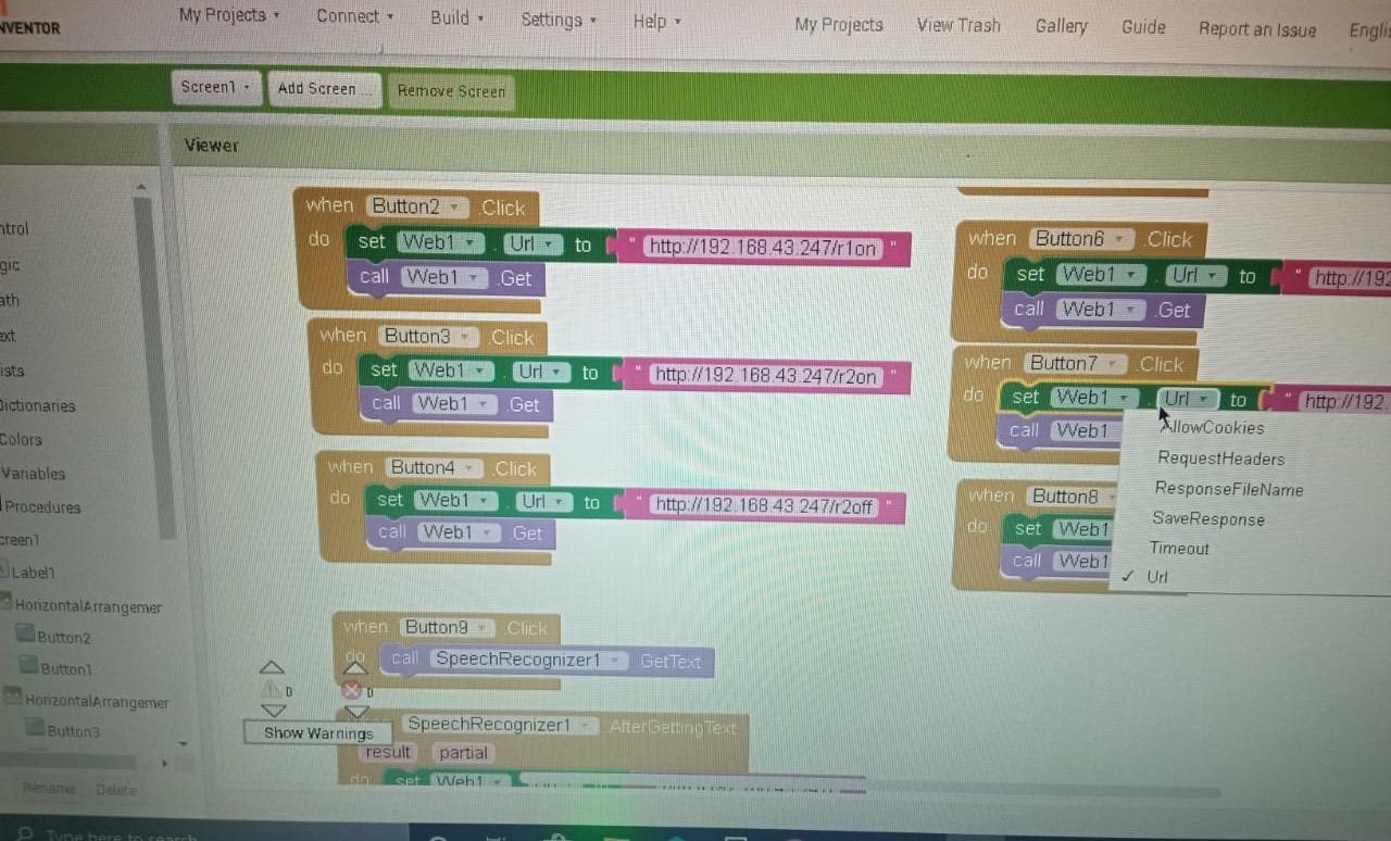 |
Home Automation App Download Link:
If you are a beginner and you don’t know to make any Android App, you can simply download the App from the link below.
http://ai2.appinventor.mit.edu/b/488y
Code to find NodeMCU IP Address
Simply copy the code provided below and upload it to Arduino IDE. After Code is uploaded successfully. Simply click on Serial Monitor and get the IP address of NodeMCU. Now note down this IP as it is required for your Android App.
Code to find NodeMCU IP Address:#include <ESP8266WiFi.h>
WiFiClient client;
WiFiServer server(80);
const char* ssid = "xxxxxxx";
const char* password = "xxxxxxx";

void setup()
{
Serial.begin(115200);
connectWiFi();
server.begin();
}

void loop()
{
}

/* connecting WiFi */
void connectWiFi()
{
Serial.println("Connecting to WIFI");
WiFi.begin(ssid, password);
while ((!(WiFi.status() == WL_CONNECTED)))
{
delay(300);
Serial.print("..");
}
Serial.println("");
Serial.println("WiFi connected");
Serial.println("NodeMCU Local IP is : ");
Serial.print((WiFi.localIP()));
}
IoT Based Voice Controlled Home Automation Using NodeMCU & AndroidSource Code/Program:#include <ESP8266WiFi.h>
WiFiClient client;
WiFiServer server(80);
const char* ssid = "xxxxxxxx";
const char* password = "xxxxxxxx";
String  command =""; // Command received from Android device

// Set Relay Pins
int relay1 = D1;
int relay2 = D2;
int relay3 = D3;
int relay4 = D4;

void setup()
{
  Serial.begin(115200);

  pinMode(relay1, OUTPUT);
  pinMode(relay2, OUTPUT);
  pinMode(relay3, OUTPUT);
  pinMode(relay4, OUTPUT);

  digitalWrite(relay1,HIGH);
  digitalWrite(relay2,HIGH);
  digitalWrite(relay3,HIGH);
  digitalWrite(relay4,HIGH);

  connectWiFi();
  server.begin();
}

void loop()
{
    client = server.available();
    if (!client) return;
    command = checkClient ();

         if (command == "r1on"  || command == "turn on relay 1"    || command == "relay 1 on")        digitalWrite(relay1,0);
    else if (command == "r1off" || command == "turn off relay 1" || command == "relay 1 off")     digitalWrite(relay1,1);
    else if (command == "r2on"  || command == "turn on relay 2"    || command == "relay 2 on")      digitalWrite(relay2,0);
    else if (command == "r2off" || command == "turn off relay 2" || command == "relay 2 off")   digitalWrite(relay2,1);
    else if (command == "r3on"  || command == "turn on relay 3"    || command == "relay 3 on")      digitalWrite(relay3,0);
    else if (command == "r3off" || command == "turn off relay 3" || command == "relay 3 off")   digitalWrite(relay3,1);
    else if (command == "r4on"  || command == "turn on relay 4"    || command == "relay 4 on")    digitalWrite(relay4,0);
    else if (command == "r4off" || command == "turn off relay 4" || command == "relay 4 off") digitalWrite(relay4,1);
    else if (command == "allon" || command == "Turn on all devices" || command == "all on")
    {
      digitalWrite(relay1,LOW);
      digitalWrite(relay2,LOW);
      digitalWrite(relay3,LOW);
      digitalWrite(relay4,LOW);
    }
    else if (command == "alloff" || command == "Turn off all devices" || command == "all off")
    {
      digitalWrite(relay1,HIGH);
      digitalWrite(relay2,HIGH);
      digitalWrite(relay3,HIGH);
      digitalWrite(relay4,HIGH);
    }
    sendBackEcho(command); // send command echo back to android device
    command = "";
}

/* connecting WiFi */
void connectWiFi()
{
  Serial.println("Connecting to WIFI");
  WiFi.begin(ssid, password);
  while ((!(WiFi.status() == WL_CONNECTED)))
  {
    delay(300);
    Serial.print("..");
  }
  Serial.println("");
  Serial.println("WiFi connected");
  Serial.println("NodeMCU Local IP is : ");
  Serial.print((WiFi.localIP()));
}

/* check command received from Android Device */
String checkClient (void)
{
  while(!client.available()) delay(1);
  String request = client.readStringUntil('\r');
  request.remove(0, 5);
  request.remove(request.length()-9,9);
  return request;
}

/* send command echo back to android device */
void sendBackEcho(String echo)
{
  client.println("HTTP/1.1 200 OK ");
  client.println("Content-Type: text/html");
  client.println("");
  client.println("<!DOCTYPE HTML>");
  client.println("<html>");
  client.println(echo);
  client.println("</html>");
  client.stop();
  delay(1);
}
- Get link
- X
- Other Apps

Comments
Post a Comment